|
  Connect to YouTube?  Connect to YouTube?  Connect to YouTube?  Connect to YouTube?  Connect to YouTube?  Connect to YouTube? Bluetooth accelerometerThe Bluetooth accelerometer is made on the basis of the Arduino Nano platform, the ADXL335 accelerometer module and HM-10 Bluetooth module supporting Bluetooth 4.0 LE (HC-06, HC-05 modules CANNOT be used). Even if you have never heard of Arduino, this will be excellent reason to become familiar with it. Here we will not be providing a detailed description of the Arduino, as the Internet contains a huge amount of information about it, but you will find references to the most important information. The main advantage of Bluetooth over Wi-Fi is its very small power consumption. However, Bluetooth module has very low data transmission rates, and therefore the transmitted data must be meticulously optimized. Data compression is based on calculation of the difference between adjacent values and the transmission of only this difference via Bluetooth. As a result, just one byte is sufficient for the transmission of a value. This ensures the presence of a maximum sampling rate of about 1870 Hz (when measuring 1 axis). Advantages of connecting an accelerometer via Bluetooth, as compared to connection via a headphone jack: • Measurement of not only vibrations, but also of absolute values. Disadvantages: • Lower sensitivity (this does not apply to accelerometers with digital output (BMA180, LSM9DS1)). Can be increased by 100 times. Connecting the Arduino Nano to a PC and downloading the sketch
Download the Arduino IDE Sketch 1:
///////////////////////////////
// © 2017 Dmitriy Kharutskiy //
///////////////////////////////

byte ByteArr[20];
int i = 0;
int ii = 0;
int AccelValue = 0;
int LastAccelValue = 0;
int dValue = 0;

void setup()
{
	//Put your setup code here, to run once:

	//Opens serial port, sets data rate.
	Serial.begin(9600);
	//Serial.begin(115200);

	//A5 => High impedance
	pinMode(A5, INPUT);
	digitalWrite(A5, LOW);
	//A5 => (+)
	//pinMode(A5, OUTPUT);
	//digitalWrite(A5, HIGH);

	//A1 => GND
	pinMode(A1, OUTPUT);
	digitalWrite(A1, LOW);

	//A0 => High impedance
	//pinMode(A0, INPUT);
	//digitalWrite(A0, LOW);

	//Configures the reference voltage used for analog input (i.e. the value used as the top of the input range).
	analogReference(EXTERNAL); //EXTERNAL: the voltage applied to the AREF pin (0 to 5V only) is used as the reference.

	//D4 => (+)
	pinMode(4, OUTPUT);
	digitalWrite(4, HIGH);

	//D5 => GND
	pinMode(5, OUTPUT);
	digitalWrite(5, LOW);

	delay(500); //Pauses the program for the amount of time (in miliseconds) specified as parameter.
}

void loop()
{
	//Put your main code here, to run repeatedly:

	AccelValue = analogRead(A3); //Reads the value from the specified analog pin. This means that it will map input voltages between 0V and reference voltage into integer values between 0 and 1023.

	if (i < 3)
	{
		ByteArr[ii] = char(-128);
		i++;
		ii++;
		ByteArr[ii] = highByte(AccelValue);
		i++;
		ii++;
		ByteArr[ii] = lowByte(AccelValue);
	}
	else
	{
		dValue = AccelValue - LastAccelValue;
		if (abs(dValue) > 127)
		{
			ByteArr[ii] = char(-128);
			i++;
			ii++;
			WriteFunction();

			ByteArr[ii] = highByte(AccelValue);
			i++;
			ii++;
			WriteFunction();

			ByteArr[ii] = lowByte(AccelValue);
		}
		else
		{
			ByteArr[ii] = char(dValue);
		}
	}
	LastAccelValue = AccelValue;

	i++;
	ii++;
	WriteFunction();

	//delay(3); //~319 Hz.
	delayMicroseconds(1000); //~880 Hz. MAX for Serial.begin(9600). delayMicroseconds(1000) = delay(1)
	//delayMicroseconds(400); //Serial.begin(115200), ~1867 Hz. MAX
}

void WriteFunction()
{
	if (ii == 20)
	{
		Serial.write(ByteArr, ii);
		ii = 0;
	}

	if (i >= 200)
	{
		i = 0;
	}
}
 
During downloading of the sketch via USB, the TXD and RXD pins must be free. If your accelerometer module differs from mine, and its contacts are located in different places, then the pin numbers of the Arduino Nano must be changed in the sketch. Assembling the Bluetooth accelerometer       
Wiring: Arduino Nano to HM-10 module Arduino Nano to ADXL335 module ADXL335 module Arduino Nano Digital Pins The ADXL335 accelerometer module is equipped with a voltage regulator. Upon connection to it of voltages over 3.6 V, the voltage regulator starts generating noise that is visible in the measurement results. 
To reduce the voltage in the accelerometer, it must be connected to a 4.5 V supply via a resistor. Noise is also visible in measurements when the accelerometer is connected to the "3V3" pin.  Noise from voltage regulator. More severe noise can come from the Bluetooth module (read below).  Connection to a 4.5 V supply via a resistor. For testing purposes, such values are specified in the settings as to show the magnitudes received from the analog-to-digital converter (without conversion to volts or acceleration). 
To increase the sensitivity of the analog input, the reference voltage is made twice lower than the supply voltage. It is done via a voltage divider consisting of two identical resistors. The reference voltage is connected to the "REF" pin. Please note that the resistor pins must not come into contact with each other under any circumstances. For convenience, resistors can be inserted using needle-nose pliers. 
Setting up the application
1: 
The correctness of the sampling rate settings must definitely be checked. A vibration source with a known frequency is required for this purpose. 2: Vref = V × R2 / (R1 + R2) There is an internal 32 kOhm resistor on the "AREF" pin. R2 = 5K × 32K / (5K + 32K) = 4.32K Ohm Battery voltage in the course of operation is continuously decreased. Therefore, it is best to measure voltage (under load) using a multimeter. If voltage (under load) of one battery is 1.4 V, then the total voltage is 4.2 V. Vref = 4.2 × 4.32K / (5K + 4.32K) = 1.947 V 3 and 4:  Preliminary Technical Data ADXL335 Voltage at the accelerometer during supply via a 5K Ohm resistor is approximately equal to V × 0.7 (for example 4.2 × 0.7 = 2.94). Correctness of settings can be checked and clarified by conducting experiments while the "Only vibration" mode is switched-off. Value at the axis pointing strictly downwards shall be -1g, and +1g upon overturning of the accelerometer. 
This is difficult to do without a multimeter, due to the necessity of making simultaneous adjustments to the reference voltage and sensitivity of the accelerometer. At first, this must be done so that the difference between maximum and minimum will be approximately 2g. Then the voltage for 0g is adjusted. Setting up the HM-10 Bluetooth module to increase the data transmission rateThe Bluetooth module can be connected to a PC via a USB-UART adapter. However, this involves extra expenses and possibly unnecessary work of search for drivers and their installation. The Bluetooth module can also be configured via the Arduino Nano. However, the data transmission rate can be changed only up to 115200 bps, because SoftwareSerial does not support the 230400 bps transmission rate. Moreover, the actual increase in the transmission rate at 230400 bps is not observed, as compared to 115200 bps. And, unfortunately, SoftwareSerial cannot be used during operations of the Bluetooth accelerometer (if the sampling rate is over 500 Hz), because data sending via SoftwareSerial stops the main program for about 2 ms. SoftwareSerial Library Sketch 2:
#include <SoftwareSerial.h> //Include the SoftwareSerial library so you can use its functions.

SoftwareSerial softSerial(11, 12); //Set up a new serial port. D11 => RX (connect to TX of other device), D12 => TX (connect to RX of other device).

void setup()
{
	//Set the data rate for the SoftwareSerial port.
	//softSerial.begin(115200); //115200 bps (bits per second)
	softSerial.begin(9600); //9600 bps (bits per second)

	//Opens serial port, sets data rate.
	//Serial.begin(115200);
	Serial.begin(9600);

	//D9 => (+)
	pinMode(9, OUTPUT);
	digitalWrite(9, HIGH);

	//D10 => GND
	pinMode(10, OUTPUT);
	digitalWrite(10, LOW);
}

void loop()
{
	if (softSerial.available()) Serial.write(softSerial.read()); //If date is coming from software serial port. softSerial date => Serial.
	if (Serial.available()) softSerial.write(Serial.read()); //If data is available on hardwareserial port. Serial date => softSerial
}
   
Check if the command terminal work normally: AT  
List all the commands: AT+HELP  
Get firmware, bluetooth, HCI and LMP version: AT+VERSION  
Get/Set baud rate: AT+BAUD (AT+BAUD8 => 115200 bps, AT+BAUD4 => 9600 bps)  
Changes in the sketch 1:
. . .

void setup()
{

	. . .

	//Serial.begin(9600);
	Serial.begin(115200);

	. . .

}

void loop()
{

	. . .

	//delay(3); //~319 Hz.
	//delayMicroseconds(1000); //~880 Hz. MAX для Serial.begin(9600). delayMicroseconds(1000) = delay(1)
	delayMicroseconds(400); //Serial.begin(115200), ~1867 Hz. MAX
}

. . .
Sensitivity increase/decrease of the Arduino NanoThe reference voltage at the "REF" pin is changed to change the sensitivity of the accelerometer (analog input). If the reference voltage is too large, then there will be stairs, instead of a sine curve. In addition, very small changes will not be registered. 
If the reference voltage is too small, then the measured signal voltage can exceed the reference voltage, and then measurement result will correspond to the reference voltage. If the difference between the neighbors exceeds 10% (5% upon additional use of a laser sensor) of the reference voltage, then difference between neighbors will not fit into a byte, and data transmission via Bluetooth will be unstable. In this case, the sampling rate can be decreased (by increasing the pause between measurements). Other assembly alternativesThe Bluetooth module during data sending consumes more current. This can result in a small voltage drop in the entire device. Consequently, the reference voltage is also decreased. This results in the distortion of measurement results. The smaller the batteries and the worse they are connected, the bigger will be the distortions. To avoid this, a capacitor (~220 µF) should be connected to the Bluetooth module.  Noise from the Bluetooth module.  With a 220 µF capacitor. However, upon powering on, the capacitor charges rapidly, and the current may exceed the allowable values for the pin. And the bigger the capacity of the capacitor, the greater the probability that after some time, the pin will be burn out. Therefore, it is best to connect the power supply to the Bluetooth module directly from batteries. However, a resistor (~51 Ohm) should be added between the capacitor and the power supply plus (+) to ensure efficient operation. Moreover, the larger the capacity of the capacitor or resistance of the resistor, the more efficient will be the filter. However, if the resistance of the resistor is too large, the Bluetooth module will not receive sufficient voltage (especially if the power supply has a voltage of 3.6 V and lower). Also, very important is the condition of the capacitor contacts with the prototype board, and sometimes the capacitor should be removed from the prototype board and then re-installed. To remove noise, it is sometimes needed to renew the contacts connecting the batteries, for this purpose, both wires must be removed and re-installed. The best variant for removing noise will be using solder connections for the parts on a special prototype board.  
Changes in the sketch 1:
. . .

void setup()
{

	. . .

	//A5 => High impedance
	//pinMode(A5, INPUT);
	//digitalWrite(A5, LOW);
	//A5 => (+)
	pinMode(A5, OUTPUT);
	digitalWrite(A5, HIGH);

	. . .

	//D4 => (+)
	//pinMode(4, OUTPUT);
	//digitalWrite(4, HIGH);

	//D5 => GND
	//pinMode(5, OUTPUT);
	//digitalWrite(5, LOW);

	. . .

}

. . .
If a battery protrudes from the battery compartment, the soft material can be glued to ensure the device remains flat. 
If device size is of little consequence, then it is best to use AA batteries with a corresponding battery compartment, instead of AAA batteries. AA batteries will better provide the needed current during data transfer, and they will have lower voltage fluctuations under load. 
If it is required to reduce the weight to the maximum or reduce the device size, then a 3.6 V lithium battery can be used.  
The most expensive part in this variant is the lithium battery. Therefore, use this variant in the extreme case. The device consumes about 20 mA and the battery capacity (according to the seller) is about 1600 mAh, and therefore, such a battery will be sufficient for about three days of continuous operations. Thus, 1/2AA size batteries can be used instead of 2/3AA batteries. The battery pins can be absolutely connected to the "5V" and "GND" pins without additional wires, but this will make it more difficult to switch the power off, and battery pins can be easily broken. A piece of soft material is inserted so that the battery does not move on the pins, thus avoiding the introduction of noise and accuracy of measurement results. Laser sensorThe laser sensor enables the detection mass center displacement of the rotating part. Maximum frequency, at which it is possible to approximately determine the mark phase, is about 50 Hz. The Bluetooth accelerometer should not be assembled for only this function. A stroboscope for the accelerometer is more precise and easier to fabricate. However, a laser sensor does not have a lower limit of rotation frequency, so if the rotation frequency is less than 15 Hz, a laser sensor must be used and not a stroboscope.   
Wiring: Laser sensor Before using a laser sensor, it should be tested. For this purpose, the laser sensor is connected, instead of the ADXL335 accelerometer.   
Laser sensor to Arduino Nano If light from a lamp connected to a 220 V or 110 V mains will shine on the sensor, then the fluctuations with frequency equal to the mains frequency multiplied by 2 may be observed. Correctness of the sampling rate adjustment can be checked in this way.   
Now a strip of white adhesive tape can be glued onto a fan, and the laser sensor can be pointed towards the rotating fan.  
Please note that for stable data transfer via Bluetooth, it is required that the difference between neighbors be less than 128 (Values from the analog-to-digital converter, without conversion to volts or acceleration. Read above.). During operation of the laser sensor together with the accelerometer, the difference between neighbors is of no importance. The following circuit can be assembled after the laser sensor is checked.   
Laser sensor to Arduino Nano The other sketch should be downloaded in the Arduino Nano. During downloading of the sketch via USB, the TXD and RXD pins must be free. 
Sketch 3:
///////////////////////////////
// © 2017 Dmitriy Kharutskiy //
///////////////////////////////

byte ByteArr[20];
int i = 0;
int ii = 0;
int AccelValue = 0;
int LastAccelValue = 0;
int dValue = 0;
int LaserValue = 0;
int maxLaserValue = 0;
int minLaserValue = 1023;
int iii = 0;
int Border = 0;
boolean Mark = false;

void setup()
{
	//Put your setup code here, to run once:

 	//Opens serial port, sets data rate.
	Serial.begin(115200);

	//A5 => High impedance
	pinMode(A5, INPUT);
	digitalWrite(A5, LOW);
	//A5 => (+)
	//pinMode(A5, OUTPUT);
	//digitalWrite(A5, HIGH);

	//A1 => GND
	pinMode(A1, OUTPUT);
	digitalWrite(A1, LOW);

	//A0 => High impedance
	//pinMode(A0, INPUT);
	//digitalWrite(A0, LOW);

	//Configures the reference voltage used for analog input (i.e. the value used as the top of the input range).
	analogReference(EXTERNAL); //EXTERNAL: the voltage applied to the AREF pin (0 to 5V only) is used as the reference.

	//D4 => (+)
	pinMode(4, OUTPUT);
	digitalWrite(4, HIGH);

	//D5 => GND
	pinMode(5, OUTPUT);
	digitalWrite(5, LOW);

	delay(500); //Pauses the program for the amount of time (in miliseconds) specified as parameter.
}

void loop()
{
	//Put your main code here, to run repeatedly:

	AccelValue = analogRead(A3); //Reads the value from the specified analog pin. This means that it will map input voltages between 0V and reference voltage into integer values between 0 and 1023.
	LaserValue = analogRead(A6);

	iii++;
	if (LaserValue > maxLaserValue) maxLaserValue = LaserValue;
	if (LaserValue < minLaserValue) minLaserValue = LaserValue;
	if (iii > 2000)
	{
		Border = maxLaserValue - round((maxLaserValue - minLaserValue) / 2.0);
		iii = 0;
		maxLaserValue = 0;
		minLaserValue = 1023;
	}
	Mark = (Border > 0 && LaserValue > Border);

	if (i < 3)
	{
		ByteArr[ii] = char(-128);
		i++;
		ii++;
		ByteArr[ii] = highByte(AccelValue);
		i++;
		ii++;
		ByteArr[ii] = lowByte(AccelValue);
	}
	else
	{
		dValue = AccelValue - LastAccelValue;
		if (abs(dValue) > 63)
		{
			ByteArr[ii] = char(-128);
			i++;
			ii++;
			WriteFunction();

			ByteArr[ii] = highByte(AccelValue);
			i++;
			ii++;
			WriteFunction();

			ByteArr[ii] = lowByte(AccelValue);
		}
		else
		{
			ByteArr[ii] = char(dValue);

			if (Mark)
			{
				if (dValue >= 0) bitWrite(ByteArr[ii], 6, 1);
				else bitWrite(ByteArr[ii], 6, 0);
			}
		}
	}
	LastAccelValue = AccelValue;

	i++;
	ii++;
	WriteFunction();

	//delayMicroseconds(400); // ~1540 Hz
	delayMicroseconds(280); // ~1893 Hz
}

void WriteFunction()
{
	if (ii == 20)
	{
		Serial.write(ByteArr, ii);
		ii = 0;
	}

	if (i >= 200)
	{
		i = 0;
	}
}
The "Laser sensor" option must be definitely enabled in the app settings, when the sketch for the laser sensor is downloaded in the Arduino Nano. Sampling rate should be set at maximum (about 1890 Hz). 
Signal phase offset takes place due to the presence of an RC-circuit in the accelerometer module structure. To compensate for this offset, we can specify the value of the product of the resistor value (kOhm) and the capacitor value (nF). E.g., 32 kOhm × 100 nF = 3200. 
Please note that the RC-circuit of the accelerometer decreases or fully mitigates the fluctuations at high frequencies. Increasing the sensitivity of the accelerometerBy using operational amplifiers connected to the circuit of a DIFFERENTIAL amplifier, it is possible to amplify the USEFUL part of the signal by 100-1000 times (or more). In the video, the signal from the accelerometer was increased by 50 times. Under these conditions, the accelerometer's noise is very noticeable. The instrumentation amplifier AD623 is the finished circuit of a differential amplifier composed of three operational amplifiers. The greater part of the electronic components on the circuit below are only necessary for reducing interference. 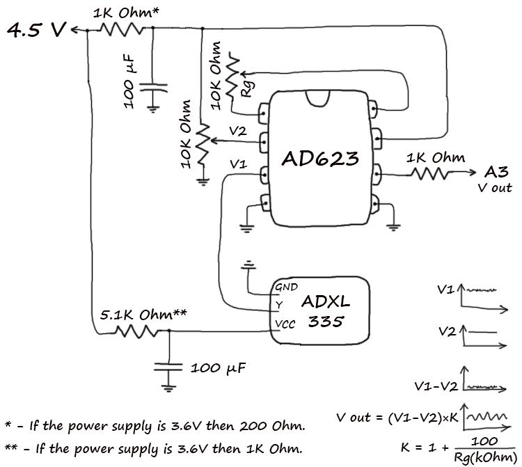        
1: Sensitivity of accelerometer × (1 + 100/Rg(kOhm)) 2: For easy tuning of the V2, it's best for this field to equal 0. But if you want to see the absolute values, then you'll need to measure the V2 and make the following calculation: (V0 - V2) × K 3-axis Bluetooth accelerometerDue to the transmission of three times the amount of data, the tri-axis Bluetooth accelerometer has a three times smaller maximum sampling rate compared to the single-axis Bluetooth accelerometer. Sketch 4 (XYZ):
///////////////////////////////
// © 2017 Dmitriy Kharutskiy //
///////////////////////////////

byte ByteArr[20];
int i = 0;
int ii = 0;
int AccelValue1 = 0;
int AccelValue2 = 0;
int AccelValue3 = 0;
int LastAccelValue1 = 0;
int LastAccelValue2 = 0;
int LastAccelValue3 = 0;
int dValue1 = 0;
int dValue2 = 0;
int dValue3 = 0;

void setup()
{
	//Put your setup code here, to run once:

	//Opens serial port, sets data rate.
	Serial.begin(9600);
	//Serial.begin(115200);

	//A5 => High impedance
	pinMode(A5, INPUT);
	digitalWrite(A5, LOW);
	//A5 => (+)
	//pinMode(A5, OUTPUT);
	//digitalWrite(A5, HIGH);

	//A1 => GND
	pinMode(A1, OUTPUT);
	digitalWrite(A1, LOW);

	//A0 => High impedance
	//pinMode(A0, INPUT);
	//digitalWrite(A0, LOW);

	//Configures the reference voltage used for analog input (i.e. the value used as the top of the input range).
	analogReference(EXTERNAL); //EXTERNAL: the voltage applied to the AREF pin (0 to 5V only) is used as the reference.

	//D4 => (+)
	pinMode(4, OUTPUT);
	digitalWrite(4, HIGH);

	//D5 => GND
	pinMode(5, OUTPUT);
	digitalWrite(5, LOW);

	delay(500); //Pauses the program for the amount of time (in miliseconds) specified as parameter.
}

void loop()
{
	//Put your main code here, to run repeatedly:

	AccelValue1 = analogRead(A4); //X-axis. Reads the value from the specified analog pin. This means that it will map input voltages between 0V and reference voltage into integer values between 0 and 1023.
	AccelValue2 = analogRead(A3); //Y-axis.
	AccelValue3 = analogRead(A2); //Z-axis.

	if (i < 7)
	{
		ByteArr[ii] = char(-128);

		i++;
		ii++;
		ByteArr[ii] = highByte(AccelValue1);
		i++;
		ii++;
		ByteArr[ii] = lowByte(AccelValue1);

		i++;
		ii++;
		ByteArr[ii] = highByte(AccelValue2);
		i++;
		ii++;
		ByteArr[ii] = lowByte(AccelValue2);

		i++;
		ii++;
		ByteArr[ii] = highByte(AccelValue3);
		i++;
		ii++;
		ByteArr[ii] = lowByte(AccelValue3);
	}
	else
	{
		dValue1 = AccelValue1 - LastAccelValue1;
		dValue2 = AccelValue2 - LastAccelValue2;
		dValue3 = AccelValue3 - LastAccelValue3;

		if (abs(dValue1) > 127 || abs(dValue2) > 127 || abs(dValue3) > 127)
		{
			ByteArr[ii] = char(-128);
			i++;
			ii++;
			WriteFunction();

			ByteArr[ii] = highByte(AccelValue1);
			i++;
			ii++;
			WriteFunction();

			ByteArr[ii] = lowByte(AccelValue1);
			i++;
			ii++;
			WriteFunction();

			ByteArr[ii] = highByte(AccelValue2);
			i++;
			ii++;
			WriteFunction();

			ByteArr[ii] = lowByte(AccelValue2);
			i++;
			ii++;
			WriteFunction();

			ByteArr[ii] = highByte(AccelValue3);
			i++;
			ii++;
			WriteFunction();

			ByteArr[ii] = lowByte(AccelValue3);
		}
		else
		{
			ByteArr[ii] = char(dValue1);
			i++;
			ii++;
			WriteFunction();

			ByteArr[ii] = char(dValue2);
			i++;
			ii++;
			WriteFunction();

			ByteArr[ii] = char(dValue3);
		}
	}
	LastAccelValue1 = AccelValue1;
	LastAccelValue2 = AccelValue2;
	LastAccelValue3 = AccelValue3;

	i++;
	ii++;
	WriteFunction();

	delay(3); //~293 Hz. MAX for Serial.begin(9600).
	//delayMicroseconds(1200); //Serial.begin(115200), ~622 Hz. MAX
}

void WriteFunction()
{
	if (ii == 20)
	{
		Serial.write(ByteArr, ii);
		ii = 0;
	}

	if (i >= 600)
	{
		i = 0;
	}
}
Sketch 5 (XY):
///////////////////////////////
// © 2017 Dmitriy Kharutskiy //
///////////////////////////////

byte ByteArr[20];
int i = 0;
int ii = 0;
int AccelValue1 = 0;
int AccelValue2 = 0;
int LastAccelValue1 = 0;
int LastAccelValue2 = 0;
int dValue1 = 0;
int dValue2 = 0;

void setup()
{
	//Put your setup code here, to run once:

	//Opens serial port, sets data rate.
	Serial.begin(9600);
	//Serial.begin(115200);

	//A5 => High impedance
	pinMode(A5, INPUT);
	digitalWrite(A5, LOW);
	//A5 => (+)
	//pinMode(A5, OUTPUT);
	//digitalWrite(A5, HIGH);

	//A1 => GND
	pinMode(A1, OUTPUT);
	digitalWrite(A1, LOW);

	//A0 => High impedance
	//pinMode(A0, INPUT);
	//digitalWrite(A0, LOW);

	//Configures the reference voltage used for analog input (i.e. the value used as the top of the input range).
	analogReference(EXTERNAL); //EXTERNAL: the voltage applied to the AREF pin (0 to 5V only) is used as the reference.

	//D4 => (+)
	pinMode(4, OUTPUT);
	digitalWrite(4, HIGH);

	//D5 => GND
	pinMode(5, OUTPUT);
	digitalWrite(5, LOW);

	delay(500); //Pauses the program for the amount of time (in miliseconds) specified as parameter.
}

void loop()
{
	//Put your main code here, to run repeatedly:

	AccelValue1 = analogRead(A4); //X-axis. Reads the value from the specified analog pin. This means that it will map input voltages between 0V and reference voltage into integer values between 0 and 1023.
	AccelValue2 = analogRead(A3); //Y-axis.

	if (i < 5)
	{
		ByteArr[ii] = char(-128);

		i++;
		ii++;
		ByteArr[ii] = highByte(AccelValue1);
		i++;
		ii++;
		ByteArr[ii] = lowByte(AccelValue1);

		i++;
		ii++;
		ByteArr[ii] = highByte(AccelValue2);
		i++;
		ii++;
		ByteArr[ii] = lowByte(AccelValue2);
	}
	else
	{
		dValue1 = AccelValue1 - LastAccelValue1;
		dValue2 = AccelValue2 - LastAccelValue2;

		if (abs(dValue1) > 127 || abs(dValue2) > 127)
		{
			ByteArr[ii] = char(-128);
			i++;
			ii++;
			WriteFunction();

			ByteArr[ii] = highByte(AccelValue1);
			i++;
			ii++;
			WriteFunction();

			ByteArr[ii] = lowByte(AccelValue1);
			i++;
			ii++;
			WriteFunction();

			ByteArr[ii] = highByte(AccelValue2);
			i++;
			ii++;
			WriteFunction();

			ByteArr[ii] = lowByte(AccelValue2);
		}
		else
		{
			ByteArr[ii] = char(dValue1);
			i++;
			ii++;
			WriteFunction();

			ByteArr[ii] = char(dValue2);
		}
	}
	LastAccelValue1 = AccelValue1;
	LastAccelValue2 = AccelValue2;

	i++;
	ii++;
	WriteFunction();

	delay(2); //~440 Hz. MAX для Serial.begin(9600).
	//delayMicroseconds(800); //Serial.begin(115200), ~934 Hz. MAX
}

void WriteFunction()
{
	if (ii == 20)
	{
		Serial.write(ByteArr, ii);
		ii = 0;
	}

	if (i >= 400)
	{
		i = 0;
	}
}
Connecting the BMA180 accelerometerIn addition to analogue output accelerometers, accelerometers with digital (I2C, SPI) output can also be used. The BMA180 accelerometer is offered as an example because of its very high sensitivity. The BMA180 accelerometer is very effective in stabilizing power supply voltage fluctuations, thus eliminating the need for a capacitor. There is also no need for resistors establishing base voltage.    
Please keep in mind that the BMA180 accelerometer is powered by a 3.3V power supply. Wiring: Arduino Nano to BMA180 accelerometer Arduino Nano to HM-10 module 
1: 1024 / 5460 = 0.188 
2: 1000 3: G-range. Sample code Sketch 6:
///////////////////////////////
// © 2017 Dmitriy Kharutskiy //
///////////////////////////////

// BMA180 triple axis accelerometer sample code //
// http://www.geeetech.com/wiki/index.php/BMA180_Triple_Axis_Accelerometer_Breakout //

#include <Wire.h>
#define BMA180 0x40  //Address of the accelerometer
#define RESET 0x10
#define PWR 0x0D
#define BW 0x20
#define RANGE 0x35
//#define DATA 0x02
#define DATA_X 0x02
#define DATA_Y 0x04
#define DATA_Z 0x06


//************************************************************
// General settings
//************************************************************

#define BandWidth B0111 // Page 28 of the datasheet for the BMA180

//#define AccelRange B000 // +/- 1g (Page 28)
#define AccelRange B001 // +/- 1.5g
//#define AccelRange B010 // +/- 2g
//#define AccelRange B011 // +/- 3g
//#define AccelRange B100 // +/- 4g
//#define AccelRange B101 // +/- 8g
//#define AccelRange B110 // +/- 16g

bool AxisX = true;
bool AxisY = false;
bool AxisZ = false;

int offx = 0;

//************************************************************


byte ByteArr[20];
int i = 0;
int ii = 0;
int AccelValue = 0;
int LastAccelValue = 0;
int dValue = 0;

void setup()
{
	//Put your setup code here, to run once:

	//Opens serial port, sets data rate.
	//Serial.begin(9600);
	Serial.begin(115200);

	//A0 => GND
	pinMode(A0, OUTPUT);
	digitalWrite(A0, LOW);
	//A1 => High impedance
	pinMode(A1, INPUT);
	digitalWrite(A1, LOW);
	//A2 => High impedance
	pinMode(A2, INPUT);
	digitalWrite(A2, LOW);
	//A3 => High impedance
	pinMode(A3, INPUT);
	digitalWrite(A3, LOW);

	//D3 => GND
	pinMode(3, OUTPUT);
	digitalWrite(3, LOW);
	//D7 => GND
	pinMode(7, OUTPUT);
	digitalWrite(7, LOW);

	//Initializing sensors
	Wire.begin();
	AccelerometerInit();

	delay(500); //Pauses the program for the amount of time (in miliseconds) specified as parameter.
}

void loop()
{
	//Put your main code here, to run repeatedly:

	AccelValue = AccelerometerRead();

	if (i < 3)
	{
		ByteArr[ii] = char(-128);
		i++;
		ii++;
		ByteArr[ii] = highByte(AccelValue);
		i++;
		ii++;
		ByteArr[ii] = lowByte(AccelValue);
	}
	else
	{
		dValue = AccelValue - LastAccelValue;
		if (abs(dValue) > 127)
		{
			ByteArr[ii] = char(-128);
			i++;
			ii++;
			WriteFunction();

			ByteArr[ii] = highByte(AccelValue);
			i++;
			ii++;
			WriteFunction();

			ByteArr[ii] = lowByte(AccelValue);
		}
		else
		{
			ByteArr[ii] = char(dValue);
		}
	}
	LastAccelValue = AccelValue;

	i++;
	ii++;
	WriteFunction();

	//delayMicroseconds(500); // ~820 Hz.
	//delayMicroseconds(400); // ~890 Hz. MAX for Serial.begin(9600)
	//delayMicroseconds(200); // ~1100 Hz.
	//delayMicroseconds(100); // ~1220 Hz.
	delayMicroseconds(10); // ~1370 Hz.
}

//************************************************************
// Functions
//************************************************************

//Initializing sensors
void AccelerometerInit()
{
	byte temp[1];
	byte temp1;

	writeTo(BMA180, RESET, 0xB6);

	// Wake up mode
	writeTo(BMA180, PWR, 0x10);

	// Band width,
	readFrom(BMA180, BW, 1, temp);
	temp1 = (temp[0] & 0x0F) | (BandWidth << 4);
	writeTo(BMA180, BW, temp1);

	// Acceleration range
	readFrom(BMA180, RANGE, 1, temp);
	temp1 = (temp[0] & 0xF1) | (AccelRange << 1);
	writeTo(BMA180, RANGE, temp1);
}

//Writes val to address register on ACC
void writeTo(int DEVICE, byte address, byte val)
{
	Wire.beginTransmission(DEVICE); //start transmission to ACC
	Wire.write(address); //send register address
	Wire.write(val); //send value to write
	Wire.endTransmission(); //end transmission
}

//Reads num bytes starting from address register in to buff array
void readFrom(int DEVICE, byte address, int num, byte buff[])
{
	Wire.beginTransmission(DEVICE); //start transmission to ACC
	Wire.write(address); //send register address
	Wire.endTransmission(); //end transmission

	Wire.beginTransmission(DEVICE); //start transmission to ACC
	Wire.requestFrom(DEVICE, num); //request num byte from ACC

	int i = 0;
	while(Wire.available()) //ACC may abnormal
	{
		buff[i] = Wire.read(); //receive a byte
		i++;
	}
	Wire.endTransmission(); //end transmission
}

//Read in the 1 axis data, each one is 14 bits
int AccelerometerRead()
{
	int n = 2;
	byte result[2];
	byte AxisAddress = (AxisX) ? DATA_X : (AxisY) ? DATA_Y : (AxisZ) ? DATA_Z : DATA_X;

	readFrom(BMA180, AxisAddress, n, result);

	int x = ((result[0] | result[1] << 8) >> 2) + offx;

	return x + 8192;
}

void WriteFunction()
{
	if (ii == 20)
	{
		Serial.write(ByteArr, ii);
		ii = 0;
	}

	if (i >= 200)
	{
		i = 0;
	}
}
Sketch 7 (XY):
///////////////////////////////
// © 2017 Dmitriy Kharutskiy //
///////////////////////////////

// BMA180 triple axis accelerometer sample code //
// http://www.geeetech.com/wiki/index.php/BMA180_Triple_Axis_Accelerometer_Breakout //

#include <Wire.h>
#define BMA180 0x40  //Address of the accelerometer
#define RESET 0x10
#define PWR 0x0D
#define BW 0x20
#define RANGE 0x35
//#define DATA 0x02
#define DATA_X 0x02
#define DATA_Y 0x04
#define DATA_Z 0x06


//************************************************************
// General settings
//************************************************************

#define BandWidth B0111 // Page 28 of the datasheet for the BMA180

//#define AccelRange B000 // +/- 1g (Page 28)
#define AccelRange B001 // +/- 1.5g
//#define AccelRange B010 // +/- 2g
//#define AccelRange B011 // +/- 3g
//#define AccelRange B100 // +/- 4g
//#define AccelRange B101 // +/- 8g
//#define AccelRange B110 // +/- 16g

bool AxisX = true;
bool AxisY = true;
bool AxisZ = false;

int offx = 0;
int offy = 0;
int offz = 0;

//************************************************************


byte ByteArr[20];
int i = 0;
int ii = 0;
int AccelValue1 = 0;
int AccelValue2 = 0;
int LastAccelValue1 = 0;
int LastAccelValue2 = 0;
int dValue1 = 0;
int dValue2 = 0;

void setup()
{
	//Put your setup code here, to run once:

	//Opens serial port, sets data rate.
	//Serial.begin(9600);
	Serial.begin(115200);

	//A0 => GND
	pinMode(A0, OUTPUT);
	digitalWrite(A0, LOW);
	//A1 => High impedance
	pinMode(A1, INPUT);
	digitalWrite(A1, LOW);
	//A2 => High impedance
	pinMode(A2, INPUT);
	digitalWrite(A2, LOW);
	//A3 => High impedance
	pinMode(A3, INPUT);
	digitalWrite(A3, LOW);

	//D3 => GND
	pinMode(3, OUTPUT);
	digitalWrite(3, LOW);
	//D7 => GND
	pinMode(7, OUTPUT);
	digitalWrite(7, LOW);

	//Initializing sensors
	Wire.begin();
	AccelerometerInit();

	delay(500); //Pauses the program for the amount of time (in miliseconds) specified as parameter.
}

void loop()
{
	//Put your main code here, to run repeatedly:

	AccelerometerRead();

	if (i < 5)
	{
		ByteArr[ii] = char(-128);

		i++;
		ii++;
		ByteArr[ii] = highByte(AccelValue1);
		i++;
		ii++;
		ByteArr[ii] = lowByte(AccelValue1);

		i++;
		ii++;
		ByteArr[ii] = highByte(AccelValue2);
		i++;
		ii++;
		ByteArr[ii] = lowByte(AccelValue2);
	}
	else
	{
		dValue1 = AccelValue1 - LastAccelValue1;
		dValue2 = AccelValue2 - LastAccelValue2;

		if (abs(dValue1) > 127 || abs(dValue2) > 127)
		{
			ByteArr[ii] = char(-128);
			i++;
			ii++;
			WriteFunction();

			ByteArr[ii] = highByte(AccelValue1);
			i++;
			ii++;
			WriteFunction();

			ByteArr[ii] = lowByte(AccelValue1);
			i++;
			ii++;
			WriteFunction();

			ByteArr[ii] = highByte(AccelValue2);
			i++;
			ii++;
			WriteFunction();

			ByteArr[ii] = lowByte(AccelValue2);
		}
		else
		{
			ByteArr[ii] = char(dValue1);
			i++;
			ii++;
			WriteFunction();

			ByteArr[ii] = char(dValue2);
		}
	}
	LastAccelValue1 = AccelValue1;
	LastAccelValue2 = AccelValue2;

	i++;
	ii++;
	WriteFunction();

	//delayMicroseconds(1000); //~465 Hz. MAX for Serial.begin(9600).
	delayMicroseconds(1); //Serial.begin(115200), ~890 Hz. MAX.
}

//************************************************************
// Functions
//************************************************************

//Initializing sensors
void AccelerometerInit()
{
	byte temp[1];
	byte temp1;

	writeTo(BMA180, RESET, 0xB6);

	// Wake up mode
	writeTo(BMA180, PWR, 0x10);

	// Band width,
	readFrom(BMA180, BW, 1, temp);
	temp1 = (temp[0] & 0x0F) | (BandWidth << 4);
	writeTo(BMA180, BW, temp1);

	// Acceleration range
	readFrom(BMA180, RANGE, 1, temp);
	temp1 = (temp[0] & 0xF1) | (AccelRange << 1);
	writeTo(BMA180, RANGE, temp1);
}

//Writes val to address register on ACC
void writeTo(int DEVICE, byte address, byte val)
{
	Wire.beginTransmission(DEVICE); //start transmission to ACC
	Wire.write(address); //send register address
	Wire.write(val); //send value to write
	Wire.endTransmission(); //end transmission
}

//Reads num bytes starting from address register in to buff array
void readFrom(int DEVICE, byte address, int num, byte buff[])
{
	Wire.beginTransmission(DEVICE); //start transmission to ACC
	Wire.write(address); //send register address
	Wire.endTransmission(); //end transmission

	Wire.beginTransmission(DEVICE); //start transmission to ACC
	Wire.requestFrom(DEVICE, num); //request num byte from ACC

	int i = 0;
	while(Wire.available()) //ACC may abnormal
	{
		buff[i] = Wire.read(); //receive a byte
		i++;
	}
	Wire.endTransmission(); //end transmission
}

//Read in the 3 axis data, each one is 14 bits
void AccelerometerRead()
{
	int n = 6;
	byte result[6];

	readFrom(BMA180, DATA_X, n, result);

	int x = ((result[0] | result[1] << 8) >> 2) + offx;
	x = x + 8192;

	int y = ((result[2] | result[3] << 8) >> 2) + offy;
	y = y + 8192;

	int z = ((result[4] | result[5] << 8) >> 2) + offz;
	z = z + 8192;

  AccelValue1 = (AxisX) ? x : (AxisY && AxisZ) ? y : x;
  AccelValue2 = (AxisY && AxisX) ? y : (AxisZ) ? z : y;
}

void WriteFunction()
{
	if (ii == 20)
	{
		Serial.write(ByteArr, ii);
		ii = 0;
	}

	if (i >= 400)
	{
		i = 0;
	}
}
Sketch 8 (XYZ):
///////////////////////////////
// © 2017 Dmitriy Kharutskiy //
///////////////////////////////

// BMA180 triple axis accelerometer sample code //
// http://www.geeetech.com/wiki/index.php/BMA180_Triple_Axis_Accelerometer_Breakout //

#include <Wire.h>
#define BMA180 0x40  //Address of the accelerometer
#define RESET 0x10
#define PWR 0x0D
#define BW 0x20
#define RANGE 0x35
//#define DATA 0x02
#define DATA_X 0x02
#define DATA_Y 0x04
#define DATA_Z 0x06


//************************************************************
// General settings
//************************************************************

#define BandWidth B0111 // Page 28 of the datasheet for the BMA180

//#define AccelRange B000 // +/- 1g (Page 28)
#define AccelRange B001 // +/- 1.5g
//#define AccelRange B010 // +/- 2g
//#define AccelRange B011 // +/- 3g
//#define AccelRange B100 // +/- 4g
//#define AccelRange B101 // +/- 8g
//#define AccelRange B110 // +/- 16g

int offx = 0;
int offy = 0;
int offz = 0;

//************************************************************


byte ByteArr[20];
int i = 0;
int ii = 0;
int AccelValue1 = 0;
int AccelValue2 = 0;
int AccelValue3 = 0;
int LastAccelValue1 = 0;
int LastAccelValue2 = 0;
int LastAccelValue3 = 0;
int dValue1 = 0;
int dValue2 = 0;
int dValue3 = 0;

void setup()
{
	//Put your setup code here, to run once:

	//Opens serial port, sets data rate.
	//Serial.begin(9600);
	Serial.begin(115200);

	//A0 => GND
	pinMode(A0, OUTPUT);
	digitalWrite(A0, LOW);
	//A1 => High impedance
	pinMode(A1, INPUT);
	digitalWrite(A1, LOW);
	//A2 => High impedance
	pinMode(A2, INPUT);
	digitalWrite(A2, LOW);
	//A3 => High impedance
	pinMode(A3, INPUT);
	digitalWrite(A3, LOW);

	//D3 => GND
	pinMode(3, OUTPUT);
	digitalWrite(3, LOW);
	//D7 => GND
	pinMode(7, OUTPUT);
	digitalWrite(7, LOW);

	//Initializing sensors
	Wire.begin();
	AccelerometerInit();

	delay(500); //Pauses the program for the amount of time (in miliseconds) specified as parameter.
}

void loop()
{
	//Put your main code here, to run repeatedly:

	AccelerometerRead();

	if (i < 7)
	{
		ByteArr[ii] = char(-128);

		i++;
		ii++;
		ByteArr[ii] = highByte(AccelValue1);
		i++;
		ii++;
		ByteArr[ii] = lowByte(AccelValue1);

		i++;
		ii++;
		ByteArr[ii] = highByte(AccelValue2);
		i++;
		ii++;
		ByteArr[ii] = lowByte(AccelValue2);

		i++;
		ii++;
		ByteArr[ii] = highByte(AccelValue3);
		i++;
		ii++;
		ByteArr[ii] = lowByte(AccelValue3);
	}
	else
	{
		dValue1 = AccelValue1 - LastAccelValue1;
		dValue2 = AccelValue2 - LastAccelValue2;
		dValue3 = AccelValue3 - LastAccelValue3;

		if (abs(dValue1) > 127 || abs(dValue2) > 127 || abs(dValue3) > 127)
		{
			ByteArr[ii] = char(-128);
			i++;
			ii++;
			WriteFunction();

			ByteArr[ii] = highByte(AccelValue1);
			i++;
			ii++;
			WriteFunction();

			ByteArr[ii] = lowByte(AccelValue1);
			i++;
			ii++;
			WriteFunction();

			ByteArr[ii] = highByte(AccelValue2);
			i++;
			ii++;
			WriteFunction();

			ByteArr[ii] = lowByte(AccelValue2);
			i++;
			ii++;
			WriteFunction();

			ByteArr[ii] = highByte(AccelValue3);
			i++;
			ii++;
			WriteFunction();

			ByteArr[ii] = lowByte(AccelValue3);
		}
		else
		{
			ByteArr[ii] = char(dValue1);
			i++;
			ii++;
			WriteFunction();

			ByteArr[ii] = char(dValue2);
			i++;
			ii++;
			WriteFunction();

			ByteArr[ii] = char(dValue3);
		}
	}
	LastAccelValue1 = AccelValue1;
	LastAccelValue2 = AccelValue2;
	LastAccelValue3 = AccelValue3;

	i++;
	ii++;
	WriteFunction();

	//delay(2); //~310 Hz. MAX for Serial.begin(9600).
	delayMicroseconds(650); //Serial.begin(115200), ~550 Hz. MAX.
}

//************************************************************
// Functions
//************************************************************

//Initializing sensors
void AccelerometerInit()
{
	byte temp[1];
	byte temp1;

	writeTo(BMA180, RESET, 0xB6);

	// Wake up mode
	writeTo(BMA180, PWR, 0x10);

	// Band width,
	readFrom(BMA180, BW, 1, temp);
	temp1 = (temp[0] & 0x0F) | (BandWidth << 4);
	writeTo(BMA180, BW, temp1);

	// Acceleration range
	readFrom(BMA180, RANGE, 1, temp);
	temp1 = (temp[0] & 0xF1) | (AccelRange << 1);
	writeTo(BMA180, RANGE, temp1);
}

//Writes val to address register on ACC
void writeTo(int DEVICE, byte address, byte val)
{
	Wire.beginTransmission(DEVICE); //start transmission to ACC
	Wire.write(address); //send register address
	Wire.write(val); //send value to write
	Wire.endTransmission(); //end transmission
}

//Reads num bytes starting from address register in to buff array
void readFrom(int DEVICE, byte address, int num, byte buff[])
{
	Wire.beginTransmission(DEVICE); //start transmission to ACC
	Wire.write(address); //send register address
	Wire.endTransmission(); //end transmission

	Wire.beginTransmission(DEVICE); //start transmission to ACC
	Wire.requestFrom(DEVICE, num); //request num byte from ACC

	int i = 0;
	while(Wire.available()) //ACC may abnormal
	{
		buff[i] = Wire.read(); //receive a byte
		i++;
	}
	Wire.endTransmission(); //end transmission
}

//Read in the 3 axis data, each one is 14 bits
void AccelerometerRead()
{
	int n = 6;
	byte result[6];

	readFrom(BMA180, DATA_X, n, result);

	int x = ((result[0] | result[1] << 8) >> 2) + offx;
	AccelValue1 = x + 8192;

	int y = ((result[2] | result[3] << 8) >> 2) + offy;
	AccelValue2 = y + 8192;

	int z = ((result[4] | result[5] << 8) >> 2) + offz;
	AccelValue3 = z + 8192;
}

void WriteFunction()
{
	if (ii == 20)
	{
		Serial.write(ByteArr, ii);
		ii = 0;
	}

	if (i >= 600)
	{
		i = 0;
	}
}
Bluetooth accelerometer based on Arduino Nano 33 BLE  
Arduino Nano 33 BLE Use ONLY the old ArduinoBLE library (ArduinoBLE ver. 1.1.2) and old core for Arduino Nano 33 BLE (Arduino Mbed OS Boards ver. 1.1.3), see screenshots below. When using a new library (ArduinoBLE ver. 1.1.3) a new core (Arduino Mbed OS Boards ver. 1.1.6), incorrect data is obtained (the sampling rate is constantly changing and is absolutely not correct). Old versions of the library and core can be selected in the settings (Installing Additional Arduino Libraries, Installing additional cores). Do not install components for Arduino Nano 33 BLE automatically offered by Arduino IDE. To check the stability of the sampling rate, you can measure the vibration frequency of a rotating external hard drive. The peak of the vibration frequency should not change the frequency for several minutes.  Tools > Manager Libraries...  Tools > Board > Boards Manager... Arduino Nano 33 BLE is very different from Arduino Nano, for example: • Do not connect a voltage greater than 3.3V to the pins (in particular to the “+5V” pin). There are differences between the built-in Arduino Nano 33 BLE Bluetooth and the HM-10 module: • I did not find an easy way to configure the Bluetooth built-in in the Arduino Nano 33 BLE (nRF52840). While the HM-10 module can be easily configured through AT commands. The sketch is adapted for smartphones with Bluetooth 4.2 and Bluetooth 5.0. These are smartphones starting with the iPhone 6S. If the iPhone only supports Bluetooth 4.0, then in the sketch you need to change the size of the transmitted packet to 20 (bufferSize = 20). For smartphones with Bluetooth 4.2 and Bluetooth 5.0, the sampling rate (when measuring 3 axes) is limited by the maximum sampling frequency of the built-in accelerometer (476 Hz, 952 Hz did not work). For smartphones with Bluetooth 4.0, the maximum sampling frequency is 119 Hz (when measuring 3 axes) and 238 Hz (when measuring 1 axis). If the Arduino Nano 33 BLE is used without a case, then in order not to stain the board with beeswax (with which the board is glued to the mechanism under study), a special adhesive tape that does not leave traces should be glued to the board. The easiest option is a GOOD masking tape. But unfortunately, beeswax does not adhere well to such a tape, and therefore the contact surface should be large. Power is connected via a USB connector. At the same time, the Arduino Nano 33 BLE works when connecting voltage from 4.1V to 5V. 5V is indicated in the description of the Arduino Nano 33 BLE, but it was tested when connecting 6.0V via USB for 7 hours and the board did not burn out.
1: For ±2 g, 1024/16384 = 0.0625 2: 1000 3: For ±2 g, 2 Sketch 9 (XYZ):
///////////////////////////////
// © 2020 Dmitriy Kharutskiy //
///////////////////////////////

// BMA180 triple axis accelerometer sample code //
// http://www.geeetech.com/wiki/index.php/BMA180_Triple_Axis_Accelerometer_Breakout //

#include <Wire.h>
#include <ArduinoBLE.h>

#define ACCELEROMETER_ADDRESS 0x6B // Address of the accelerometer
#define ACCELEROMETER_STATUS_REG 0x17 // (Page 49 of the datasheet for the LSM9DS1, STATUS_REG)
#define DATA_X 0x28 // (Page 56, OUT_X_L_XL)
#define DATA_Y 0x2A // (Page 56, OUT_Y_L_XL)
#define DATA_Z 0x2C // (Page 56, OUT_Z_L_XL)

//************************************************************
// General settings
//************************************************************

#define ACCELEROMETER_SETTINGS_ADDRESS 0x20 // (Page 51 of the datasheet for the LSM9DS1, CTRL_REG6_XL)
//#define ACCELEROMETER_SETTINGS B10100000 // B[101]00000 - 476 Hz, B101[00]000 - 2 G (Page 51-52 of the datasheet for the LSM9DS1, CTRL_REG6_XL)
//#define ACCELEROMETER_SETTINGS B10110000 // B[101]10000 - 476 Hz, B101[10]000 - 4 G
//#define ACCELEROMETER_SETTINGS B10111000 // B[101]11000 - 476 Hz, B101[11]000 - 8 G
#define ACCELEROMETER_SETTINGS B10101000 // B[101]01000 - 476 Hz, B101[01]000 - 16 G
//#define ACCELEROMETER_SETTINGS B10011000 // B[100]11000 - 238 Hz, B100[11]000 - 8 G
//#define ACCELEROMETER_SETTINGS B01111000 // B[011]11000 - 119 Hz, B011[11]000 - 8 G
//#define ACCELEROMETER_SETTINGS B11011000 // B[110]11000 - 952 Hz, B110[11]000 - 8 G // DOES NOT WORK. The test shows 476 Hz instead of 952 Hz.

#define ACCELEROMETER_RESET_ADDRESS 0x22 // (Page 53, CTRL_REG8)
#define ACCELEROMETER_RESET B00000101 // (Page 53, CTRL_REG8)

int16_t offx = 0;
int16_t offy = 0;
int16_t offz = 0;

const int bufferSize = 244; // For Bluetooth 4.2 and Bluetooth 5.0 https://punchthrough.com/maximizing-ble-throughput-part-3-data-length-extension-dle-2/
//const int bufferSize = 20; // For Bluetooth 4.0 https://punchthrough.com/maximizing-ble-throughput-part-3-data-length-extension-dle-2/
BLEService accelerometerService("FFE0");
BLECharacteristic accelerometerDataChar("FFE1", BLERead | BLENotify, bufferSize, true);

int dataLengthAfterMarker = bufferSize * 3;

//************************************************************


byte ByteArr[bufferSize];
int i = 0;
int ii = 0;
int16_t AccelValue1 = 0;
int16_t AccelValue2 = 0;
int16_t AccelValue3 = 0;
int16_t LastAccelValue1 = 0;
int16_t LastAccelValue2 = 0;
int16_t LastAccelValue3 = 0;
uint16_t unsignedAccelValue = 0;
int16_t dValue1 = 0;
int16_t dValue2 = 0;
int16_t dValue3 = 0;
long previousMicros = 0;


void setup()
{
	// put your setup code here, to run once:

	Serial.begin(9600);

	pinMode(LED_BUILTIN, OUTPUT); // initialize the built-in LED pin to indicate when a central is connected


	Wire1.begin();
	delay(50);


	// Initializing sensors
	initAccelerometer();

	initBLE();


	delay(500); // Pauses the program for the amount of time (in miliseconds) specified as parameter.
}

void loop()
{
	// put your main code here, to run repeatedly:


	// wait for a BLE central
	BLEDevice central = BLE.central();


	// if a central is connected to the peripheral:
	if (central)
	{
		// turn on the LED to indicate the connection:
		digitalWrite(LED_BUILTIN, HIGH);


		// while the central is connected:
		while (central.connected())
		{
			if (newDataAvailability())
			{
				/*
				// Sample rate testing
				long currentMicros = micros();
  				Serial.println(currentMicros - previousMicros);
  				previousMicros = micros();
  				*/

				readAccelerometer();
				//Serial.println(AccelValue1);

				if (i < 3)
				{
					ByteArr[ii] = char(-128);
					i++;
					ii++;

					unsignedAccelValue = AccelValue1 + 32768;
					ByteArr[ii] = highByte(unsignedAccelValue);
					i++;
					ii++;
					ByteArr[ii] = lowByte(unsignedAccelValue);

					i++;
					ii++;
					unsignedAccelValue = AccelValue2 + 32768;
					ByteArr[ii] = highByte(unsignedAccelValue);
					i++;
					ii++;
					ByteArr[ii] = lowByte(unsignedAccelValue);

					i++;
					ii++;
					unsignedAccelValue = AccelValue3 + 32768;
					ByteArr[ii] = highByte(unsignedAccelValue);
					i++;
					ii++;
					ByteArr[ii] = lowByte(unsignedAccelValue);
				}
				else
				{
					dValue1 = AccelValue1 - LastAccelValue1;
					dValue2 = AccelValue2 - LastAccelValue2;
					dValue3 = AccelValue3 - LastAccelValue3;

					if (abs(dValue1) > 127 || abs(dValue2) > 127 || abs(dValue3) > 127)
					{
						ByteArr[ii] = char(-128);
						i = 0;
						i++;
						ii++;
						sendBuffer();

						unsignedAccelValue = AccelValue1 + 32768;
						ByteArr[ii] = highByte(unsignedAccelValue);
						i++;
						ii++;
						sendBuffer();

						ByteArr[ii] = lowByte(unsignedAccelValue);
						i++;
						ii++;
						sendBuffer();

						unsignedAccelValue = AccelValue2 + 32768;
						ByteArr[ii] = highByte(unsignedAccelValue);
						i++;
						ii++;
						sendBuffer();

						ByteArr[ii] = lowByte(unsignedAccelValue);
						i++;
						ii++;
						sendBuffer();

						unsignedAccelValue = AccelValue3 + 32768;
						ByteArr[ii] = highByte(unsignedAccelValue);
						i++;
						ii++;
						sendBuffer();

						ByteArr[ii] = lowByte(unsignedAccelValue);
					}
					else
					{
						ByteArr[ii] = char(dValue1);
						i++;
						ii++;
						sendBuffer();

						ByteArr[ii] = char(dValue2);
						i++;
						ii++;
						sendBuffer();

						ByteArr[ii] = char(dValue3);
					}
				}
				LastAccelValue1 = AccelValue1;
				LastAccelValue2 = AccelValue2;
				LastAccelValue3 = AccelValue3;

				i++;
				ii++;
				sendBuffer();
			}
		}

		// when the central disconnects, turn off the LED:
		digitalWrite(LED_BUILTIN, LOW);
	}
}

//************************************************************
// Functions
//************************************************************

// Initializing sensors
void initAccelerometer()
{
	byte temp[1];
	byte temp1;

	// RESET
	writeTo(ACCELEROMETER_ADDRESS, ACCELEROMETER_RESET_ADDRESS, 0x05);

	// ACCELEROMETER SETTING: acceleration range, band width
	writeTo(ACCELEROMETER_ADDRESS, ACCELEROMETER_SETTINGS_ADDRESS, ACCELEROMETER_SETTINGS);

	delay(100);
}

// Initializing BLE
void initBLE()
{
	// begin initialization
	if (!BLE.begin())
	{
		while (1)
		{
			Serial.println("starting BLE failed!");
			delay(1000);
		}
	}

	BLE.setLocalName("Vibration_Analysis_App");
	BLE.setAdvertisedService(accelerometerService); // add the service UUID
	accelerometerService.addCharacteristic(accelerometerDataChar); // add the battery level characteristic
	BLE.addService(accelerometerService); // Add the battery service

	// start advertising
	BLE.advertise();
}


// Writes val to address register on ACC
void writeTo(int DEVICE, byte address, byte val)
{
	Wire1.beginTransmission(DEVICE); // start transmission to ACC
	Wire1.write(address); // send register address
	Wire1.write(val); // send value to write
	Wire1.endTransmission(); // end transmission
}

// Reads num bytes starting from address register in to buff array
void readFrom(int DEVICE, byte address, int num, byte buff[])
{
	Wire1.beginTransmission(DEVICE); // start transmission to ACC
	Wire1.write(address); // send register address
	Wire1.endTransmission(); // end transmission

	Wire1.beginTransmission(DEVICE); // start transmission to ACC
	Wire1.requestFrom(DEVICE, num); // request num byte from ACC

	int n = 0;
	while(Wire1.available()) // ACC may abnormal
	{
		buff[n] = Wire1.read(); // receive a byte
		n++;
	}
	Wire1.endTransmission(); // end transmission
}

// Read in the 3 axis data, each one is 16 bits
void readAccelerometer()
{
	int n = 6;
	byte result[6];

	readFrom(ACCELEROMETER_ADDRESS, DATA_X, n, result);

	AccelValue1 = int16_t(result[1] << 8 | result[0]) + offx;
	AccelValue2 = int16_t(result[3] << 8 | result[2]) + offy;
	AccelValue3 = int16_t(result[5] << 8 | result[4]) + offz;
}

void sendBuffer()
{
	if (ii == bufferSize)
	{
		long beforeMicros = micros();

		accelerometerDataChar.writeValue(ByteArr, ii);

		long afterMicros = micros();
		//Serial.println(afterMicros - beforeMicros); // Testing delay when sending data

		ii = 0;

		if (i >= dataLengthAfterMarker) i = 0;
	}
}

bool newDataAvailability()
{
	byte temp[1];
	readFrom(ACCELEROMETER_ADDRESS, ACCELEROMETER_STATUS_REG, 1, temp);

	if ((temp[0] & B00000001) != 0) return true;

	return false;
}
Sketch 10 (X):
///////////////////////////////
// © 2020 Dmitriy Kharutskiy //
///////////////////////////////

// BMA180 triple axis accelerometer sample code //
// http://www.geeetech.com/wiki/index.php/BMA180_Triple_Axis_Accelerometer_Breakout //

#include <Wire.h>
#include <ArduinoBLE.h>

#define ACCELEROMETER_ADDRESS 0x6B // Address of the accelerometer
#define ACCELEROMETER_STATUS_REG 0x17 // (Page 49 of the datasheet for the LSM9DS1, STATUS_REG)
#define DATA_X 0x28 // (Page 56, OUT_X_L_XL)
#define DATA_Y 0x2A // (Page 56, OUT_Y_L_XL)
#define DATA_Z 0x2C // (Page 56, OUT_Z_L_XL)

//************************************************************
// General settings
//************************************************************

#define ACCELEROMETER_SETTINGS_ADDRESS 0x20 // (Page 51 of the datasheet for the LSM9DS1, CTRL_REG6_XL)
//#define ACCELEROMETER_SETTINGS B10100000 // B[101]00000 - 476 Hz, B101[00]000 - 2 G (Page 51-52 of the datasheet for the LSM9DS1, CTRL_REG6_XL)
//#define ACCELEROMETER_SETTINGS B10110000 // B[101]10000 - 476 Hz, B101[10]000 - 4 G
//#define ACCELEROMETER_SETTINGS B10111000 // B[101]11000 - 476 Hz, B101[11]000 - 8 G
#define ACCELEROMETER_SETTINGS B10101000 // B[101]01000 - 476 Hz, B101[01]000 - 16 G
//#define ACCELEROMETER_SETTINGS B10011000 // B[100]11000 - 238 Hz, B100[11]000 - 8 G
//#define ACCELEROMETER_SETTINGS B01111000 // B[011]11000 - 119 Hz, B011[11]000 - 8 G
//#define ACCELEROMETER_SETTINGS B11011000 // B[110]11000 - 952 Hz, B110[11]000 - 8 G // DOES NOT WORK. The test shows 476 Hz instead of 952 Hz.

#define ACCELEROMETER_RESET_ADDRESS 0x22 // (Page 53, CTRL_REG8)
#define ACCELEROMETER_RESET B00000101 // (Page 53, CTRL_REG8)

bool AxisX = true;
bool AxisY = false;
bool AxisZ = false;

int16_t offx = 0;

const int bufferSize = 244; // For Bluetooth 4.2 and Bluetooth 5.0 https://punchthrough.com/maximizing-ble-throughput-part-3-data-length-extension-dle-2/
//const int bufferSize = 20; // For Bluetooth 4.0 https://punchthrough.com/maximizing-ble-throughput-part-3-data-length-extension-dle-2/
BLEService accelerometerService("FFE0");
BLECharacteristic accelerometerDataChar("FFE1", BLERead | BLENotify, bufferSize, true);

int dataLengthAfterMarker = bufferSize * 3;

//************************************************************


byte ByteArr[bufferSize];
int i = 0;
int ii = 0;
int16_t AccelValue = 0;
int16_t LastAccelValue = 0;
uint16_t unsignedAccelValue = 0;
int16_t dValue = 0;
long previousMicros = 0;


void setup()
{
	// put your setup code here, to run once:

	Serial.begin(9600);

	pinMode(LED_BUILTIN, OUTPUT); // initialize the built-in LED pin to indicate when a central is connected


	Wire1.begin();
	delay(50);


	// Initializing sensors
	initAccelerometer();

	initBLE();


	delay(500); // Pauses the program for the amount of time (in miliseconds) specified as parameter.
}

void loop()
{
	// put your main code here, to run repeatedly:


	// wait for a BLE central
	BLEDevice central = BLE.central();

	// if a central is connected to the peripheral:
	if (central)
	{
		// turn on the LED to indicate the connection:
		digitalWrite(LED_BUILTIN, HIGH);


		// while the central is connected:
		while (central.connected())
		{
			if (newDataAvailability())
			{
				/*
				// Sample rate testing
				long currentMicros = micros();
				Serial.println(currentMicros - previousMicros);
				previousMicros = micros();
				*/

				AccelValue = readAccelerometer();
				//Serial.println(AccelValue);

				if (i == 0)
				{
					ByteArr[ii] = char(-128);
					i++;
					ii++;

					unsignedAccelValue = AccelValue + 32768;
					ByteArr[ii] = highByte(unsignedAccelValue);
					i++;
					ii++;
					ByteArr[ii] = lowByte(unsignedAccelValue);
				}
				else
				{
					dValue = AccelValue - LastAccelValue;

					if (abs(dValue) > 127)
					{
						ByteArr[ii] = char(-128);
						i = 0;
						i++;
						ii++;
						sendBuffer();

						unsignedAccelValue = AccelValue + 32768;
						ByteArr[ii] = highByte(unsignedAccelValue);
						i++;
						ii++;
						sendBuffer();

						ByteArr[ii] = lowByte(unsignedAccelValue);
					}
					else
					{
						ByteArr[ii] = char(dValue);
					}
				}
				LastAccelValue = AccelValue;

				i++;
				ii++;
				sendBuffer();
			}
		}

		// when the central disconnects, turn off the LED:
		digitalWrite(LED_BUILTIN, LOW);
	}
}

//************************************************************
// Functions
//************************************************************

// Initializing sensors
void initAccelerometer()
{
	byte temp[1];
	byte temp1;

	// RESET
	writeTo(ACCELEROMETER_ADDRESS, ACCELEROMETER_RESET_ADDRESS, 0x05);

	// ACCELEROMETER SETTING: acceleration range, band width
	writeTo(ACCELEROMETER_ADDRESS, ACCELEROMETER_SETTINGS_ADDRESS, ACCELEROMETER_SETTINGS);

	delay(100);
}

// Initializing BLE
void initBLE()
{
	// begin initialization
	if (!BLE.begin())
	{
		while (1)
		{
			Serial.println("starting BLE failed!");
			delay(1000);
		}
	}

	BLE.setLocalName("Vibration_Analysis_App");
	BLE.setAdvertisedService(accelerometerService); // add the service UUID
	accelerometerService.addCharacteristic(accelerometerDataChar); // add the battery level characteristic
	BLE.addService(accelerometerService); // Add the battery service

	// start advertising
	BLE.advertise();
}

// Writes val to address register on ACC
void writeTo(int DEVICE, byte address, byte val)
{
	Wire1.beginTransmission(DEVICE); // start transmission to ACC
	Wire1.write(address); // send register address
	Wire1.write(val); // send value to write
	Wire1.endTransmission(); // end transmission
}

// Reads num bytes starting from address register in to buff array
void readFrom(int DEVICE, byte address, int num, byte buff[])
{
	Wire1.beginTransmission(DEVICE); // start transmission to ACC
	Wire1.write(address); // send register address
	Wire1.endTransmission(); // end transmission

	Wire1.beginTransmission(DEVICE); // start transmission to ACC
	Wire1.requestFrom(DEVICE, num); // request num byte from ACC

	int n = 0;
	while(Wire1.available()) // ACC may abnormal
	{
		buff[n] = Wire1.read(); // receive a byte
		n++;
	}
	Wire1.endTransmission(); // end transmission
}

// Read in the 1 axis data, each one is 16 bits
int16_t readAccelerometer()
{
	int n = 2;
	byte result[2];
	byte AxisAddress = (AxisX) ? DATA_X : (AxisY) ? DATA_Y : (AxisZ) ? DATA_Z : DATA_X;

	readFrom(ACCELEROMETER_ADDRESS, AxisAddress, n, result);

	int16_t x = int16_t(result[1] << 8 | result[0]) + offx;

	return x;
}

void sendBuffer()
{
	if (ii == bufferSize)
	{
		long beforeMicros = micros();

		accelerometerDataChar.writeValue(ByteArr, ii);

		long afterMicros = micros();
		//Serial.println(afterMicros - beforeMicros); // Testing delay when sending data

		ii = 0;

		if (i >= dataLengthAfterMarker) i = 0;
	}
}

bool newDataAvailability()
{
	byte temp[1];
	readFrom(ACCELEROMETER_ADDRESS, ACCELEROMETER_STATUS_REG, 1, temp);

	if ((temp[0] & B00000001) != 0) return true;

	return false;
}
Shopping    
1:  eBay: "bluetooth module hm-10" 2:  eBay: "capacitor electrolytic 220uF" 3:  AliExpress: "breadboard jumper wires 65 pcs"  AliExpress: "jump wire female to female 20cm"  eBay: "breadboard U shape jumper" 4:  eBay: "Arduino Nano" (For Mac eBay: "Arduino Nano FT232RL") 5:  eBay: "resistor 1W kit" 6:  AliExpress: "breadboard 170" 7:  eBay: "battery box 3AA switch" 8:  AliExpress: "ADXL335"  eBay: "2.54 mm 1x40 male angle connector" 9:  AliExpress: "phototransistor 3DU5C" 10:  AliExpress: "laser module red" 11:  eBay: "AD623AN" 12:  eBay: "10K 3296W" 13:  eBay: "BMA180" 14:  eBay: "AA battery box USB" 
|
| Useful Mobile Apps | ||
 |

 Vibration analysis
 BLE accelerometer
 Tachometers
 Video tachometer
 Speedometers
 DIY anemometer
 DIY metal detector
 Sound analysis
 Turns counter
 Photo Storage